顯示具有 Arduino 標籤的文章。 顯示所有文章

2017年4月19日 星期三

Arduino筆記 Lesson 4-與外部溝通第一步-TTP229 16 pin電容式按鈕

1.電容式按鈕原理

電容式觸摸感應按鍵的基本原理如圖所示,當人體接觸電極的時候,由于人體相當于一個接大地的電容,因此會在感應電極和大地方間形成一個電容CF,感應電容量通常有幾pF到幾十pF。利用這個最基本的原理,在外部搭建相關的電路,就可以根據這個電容量的變化,檢測是否有人體接觸電極。


觸控電容之原理
資料來源:http://www.digitimes.com.tw/tw/dt/n/shwnws.asp?CnlID=13&id=0000262383_JHD2DGH79LV7CB2GE8M28&ct=1&OneNewsPage=2&Page=1


2.TTP229電路解析
(1)Pin腳說明:
OUT1~OUT8實際上是Touch PAD當中的9~16....不要被騙了
SDO、SCL是 I2C的接腳
VCC是+電壓輸入
GND是地線

TTP229電路板
(2)啟動16Pin
在TP2尚未被焊接的時候,僅有Touch PAD當中的1~8被啟動,後面八個按鈕是不會動的。
經說明後,需要將上述下排,由左至右第二個JUMP短路後
才會從8Pin啟動為16Pin input。
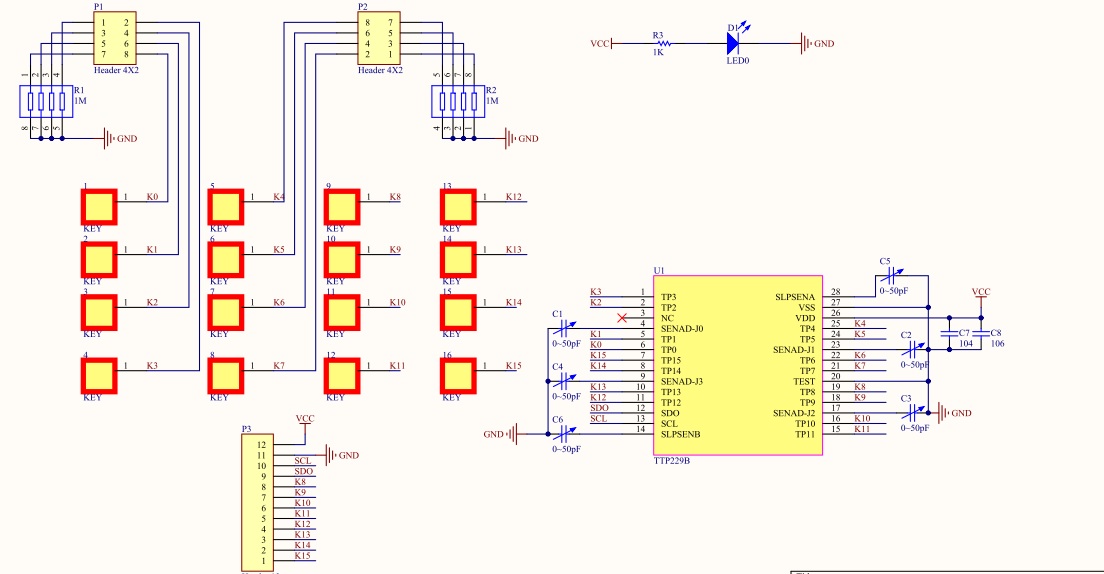
TTP229電路板的Schematic圖形

3.Arduino Nano 與TTP229的第一類接觸

資料來源:http://forum.hobbycomponents.com/viewtopic.php?f=73&t=1781&hilit=hcmodu0079
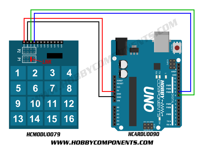
TTP229 16按鈕與Arduino UNO串接

TTP229是I2C介面,因此在UNO當中
SCL Pin腳位為8
SDO Pin腳位為9

轉換到Nano當中的I2C介面
SCL Pin腳位為19
SDO Pin腳位為18

如果說要轉換成STM32F103C8T6,則需要將腳位改寫為
   *For STM32F103C8T6 Minimum Development Board
   *SCL connected to PB8
    *SDO connected to PB9


4.程式碼撰寫
/*
  Reading a TTP229 based capacitive touch Keyboard
  to enable 16-Key Mode short TP2 with a 820kOhms (up to 1MOhms)
  Resistor to GROUND or close Jumper 3 on TP229 Module

  hardware required TTP229 Module with
  *For Arduino Nano Virtual Pin
  * SCL connected to 19
  * SDO connected to 18
   *For STM32F103C8T6 Minimum Development Board
   *SCL connected to PB8
    *SDO connected to PB9
  Adopted by Hunt Hung
  This example code is part of the public domain
*/

/* Define the digital pins used for the clock and data */
#define SCL_PIN 19
#define SDO_PIN 18

/* Used to store the key state */
byte Key;

void setup()
{
  /* Initialise the serial interface */
  Serial.begin(9600);
  /* Configure the clock and data pins */
  pinMode(SCL_PIN, OUTPUT);
  pinMode(SDO_PIN, INPUT);
}


/* Main program */
void loop()
{
  /* Read the current state of the keypad */
  Key = Read_Keypad();

  /* If a key has been pressed output it to the serial port */
  if (Key)
    Serial.println(Key);

  /* Wait a little before reading again
     so not to flood the serial port*/
  delay(100);
}


/* Read the state of the keypad */
byte Read_Keypad(void)
{
  byte Count;
  byte Key_State = 0;

  /* Pulse the clock pin 16 times (one for each key of the keypad)
     and read the state of the data pin on each pulse */
  for(Count = 1; Count <= 16; Count++)
  {
    digitalWrite(SCL_PIN, LOW);
 
    /* If the data pin is low (active low mode) then store the
       current key number */
    if (!digitalRead(SDO_PIN))
      Key_State = Count;
 
    digitalWrite(SCL_PIN, HIGH);
  }

  return Key_State;
}


5.測試與改良


當然上述的狀態是比較
實驗結果~若要外接額外的Pin腳,則資料會不斷的亂跳

6.閱讀TTP229 IC datasheet
通泰科技TTP229 IC Datasheet(英文完全版)


文中有說明到,若要修改對應鍵的靈敏度,則需要調整電容值。 CJ0~CJ3 和 CJWA~CJWB 的电容值可用于調節對應案件的靈敏度。电容值越小,靈敏度越高。灵敏度的调节必须是根据实际应用的 PCB 来做决定。电容值的取值范围是 1pF≦ CJ0~CJ3≦ 50pF  ,1pF≦ CJW  A~CJWB≦50pF。建议先通过调节 CJ0~CJ3 的容 值来调节 K0~K15 的灵敏度,再調節CJWA 和 CJWB 的容值来來調節喚醒靈敏度。

把IC對照PCBA Schematic來看,CJ0~CJ3= C1~C4,CJWA~CJWB=C5~C6,因此若要調整靈敏度,就要將C1~C4換成50pF,若再不行的話連C5~C6都要換成50pF

SMD 電容

因此在原本的電路板中,好像都是1pF的電容,因此要把他們全部都換成50pF的電容
再測試看看會不會比較穩定一點不會亂跳。

7.進階玩法:開啟TTP229之功能列
當系統可以啟動的時候,於是乎小編的友人繼續的來開啟相關隱藏功能
"有沒有可以多點觸控啊....."

於是乎再來不斷的survey相關的datasheet.....
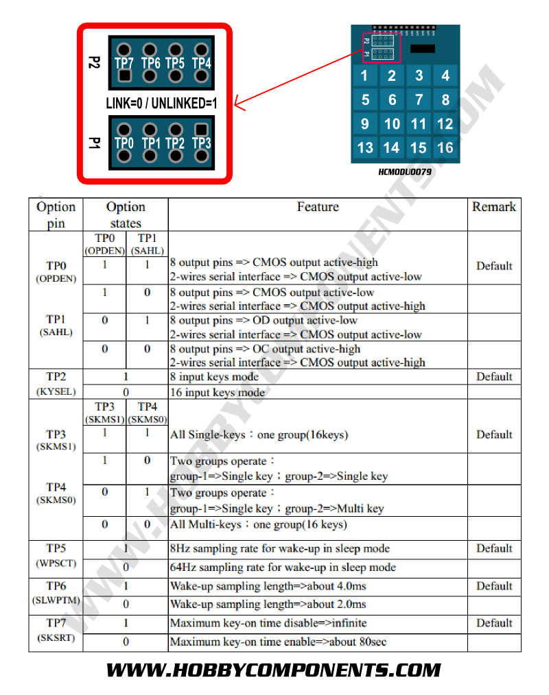
由上述可以看到,TP3~TP4的狀態有無短路,代表的是多點觸控的開始........因此銲槍打開來繼續玩......(TP3與TP4均要短路)


2017年4月18日 星期二

Arduino筆記 Lesson 3-閱讀Datasheet-STM32F103c8t6的規格


資料來源:
https://developer.mbed.org/users/hudakz/code/STM32F103C8T6_Hello/shortlogSTM32F103C8T6 board

微處理機規格
  • STM32F103C8T6 in LQFP48 package
  • ARM®32-bit Cortex®-M3 CPU
  • 72 MHz max CPU frequency
  • VDD from 2.0 V to 3.6 V
  • 64 KB Flash
  • 20 KB SRAM
  • GPIO (32) with external interrupt capability
  • 12-bit ADC (2) with 10 channels
  • RTC
  • Timers (4)
  • I2C (2)
  • USART (3)
  • SPI (2)
  • USB 2.0 full-speed
  • CAN
IC的Datasheet如連結,有機會再跟各位說明一下相關的datasheet內容

電路板規格
  • Small foot-print
  • Flexible board power supply: USB VBUS or external source (3.3V, 5V)
  • User LED: LED1 (PC13)
  • One push button: RESET
  • Programming/Debug port
  • Micro-B USB connector 

2017年4月17日 星期一

Arduino 筆記 Lesson 2 -STM32F103C8T6 - UART通訊

一、基礎連結

原文請參考http://grauonline.de/wordpress/?page_id=1004


STM32F103C8T6使用Arduino IDE 進行UART通訊成果

1.請依照下面的電路圖進行串接
在這邊要注意一點,就是電源要接上,要不然無法使用!!

2. 下載且安裝 Arduino IDE (目前最新版本為Arduino 1.8.2)

將這個資料夾解壓縮後會得到‘Arduino_STM32-master’這個資料夾,並將這個資料夾的內容放到你的Arduino硬體資料夾 (C:\Programs\Arduino\hardware).

4. 打開 Arduino IDE, 可以看到在板子的選項中可以選擇:
Board: Generic STM32F103C series
‘Variant: STM32F103C8 (20k RAM, 64k Flash)’
Upload method: Serial
‘Port: <the COM port of your USB-to-serial adapter>’

5. Compile this sketch:
#define pinLED PC13
void setup() {
  Serial.begin(9600);
  pinMode(pinLED, OUTPUT);
  Serial.println("START");  
}
void loop() {
  digitalWrite(pinLED, HIGH);
  delay(1000);
  digitalWrite(pinLED, LOW);
  Serial.println("Hello World");  
}

然後就會開始啟動。

二、多埠連結

既然STM32F103C8T6有三個USART埠,要如何啟動呢?
對於初始狀態而言,A9,A10(板子上可看到的IO)是初始USB對電腦的(TX,RX)
這個答案請參考下列

http://wiki.stm32duino.com/index.php?title=API#Serial_.26_USB_Serial

我把內容貼出來

Serial & USB Serial 
Serial USB is enabled for all F103 boards when uploading using the bootloader, it is also available when uploading by ST-Link (SWD) 
In these cases:
  • Serial.print("Hello world"); will print via Serial USB (CDC).
  • Serial1 prints to hardware USART 1
  • Serial2 prints to hardware USART 2
  • etc

換句話說若是要使用USART1,就打Serial1,要使用USART2,就打Serail2

Arduino 筆記 Lesson 1 挑選系統版

筆者因為朋友的一點小需求
所以挑選三塊板子進行相關的說明

1.Arduino Pro Mini


2.Arduino Nano
3.STM32f103c8t6 最小系統版


4. Arduino UNO R3

會選擇STM32f103c8t6的原因
除了與Arduino IDE相容以外,可以用比較快速以及簡單的語法來啟動嵌入式系統以外
還有一件很重要的事情就是,可以與既有ST Link相關的編譯軟體進行互通
換句話說,若是使用STM32f103c8t6,之後要量產的話比較有機會進行大量複製
....雖然說以Maker的角度而言好像不太需要考量所謂的量產的事情。

至於兩張板子的比較,資節錄網路上已經有人做的Performance 比較
Arduino Mini 以及 STM32F103c8t6的差別
Youtube連結如下:
https://www.youtube.com/watch?v=5mDnKBNl9sY

節錄重點:STM32F103c8t6有的Performance比Arduino Mini快將近12倍
Arduino Mini 測試結果(秒數越多代表越久)
STM32F103c8t6 測試結果 (秒數越少代表越快)
在價格部分,STM32F103c8t6來自於中國的龐大代工下的成果....所以與Arduino相比是意外的便宜,然而他的缺點就是網路上的資源相當的少

以後有空再慢慢地描述每一張板子如何使用。

零下世界-電子電路的狀態

我們分為幾個地方進行討論:在單晶片系統當中,包含了幾個元件 1.MCU 2.晶體震盪器 3.電池 下面就各個元件的狀態來說明零下的時候各個元件效應 1.MCU的工作狀態:資料來源, STM32F103 Datasheet The devices operate f...
